
Introduction — a small shop, a stubborn machine, and a question
I was in a wee workshop last winter, watching a machinist fiddle with a drive that would not behave. The device was billed as a high-efficiency electric motor, but it stuttered under load and hummed like a kettle. Recent tests show many motors lose three to seven percent of expected efficiency under real conditions (that adds up fast); so why do well‑designed units fail where it matters most? I ask because I’ve seen teams replace controllers, rewound stators and still miss the root cause — and that made me curious enough to dig in. In this piece I’ll map the scene, point out where traditional fixes fall short, and then look ahead to what truly helps. Let us move on to the technical layer — where design choices meet real use.

Part 2 — Why classic fixes for the pmsm motor often miss the mark
To begin, let me define a kernel of the problem: a permanent magnet synchronous machine (the pmsm motor) depends on tight control of current and flux to deliver steady torque. Field-oriented control and sensorless control are common tools. But those methods assume clean signals, steady supply voltage, and predictable thermal behaviour. In practice we face noisy encoders, fluctuating power converters, and slight magnet demagnetisation. When any one of those appears, torque ripple grows, thermal hotspots form, and the controller chases the wrong signal. I’ve had engineers tell me their diagnostics showed “nominal” readings — yet the motor sagged in service. Look, it’s simpler than you think: a tiny drift in back-EMF or a misread temperature can cascade into poor performance.
How do these failures show up?
Failures show as subtle symptoms at first — a soft shudder under mid-load, higher current draw at low speeds, or intermittent vibration. Those are clues. Often teams patch firmware or swap in more aggressive current limits. That helps momentarily but does not fix root causes like core losses, rotor eccentricity, or incorrect commutation timing. I’ve logged that pattern repeatedly — quick band-aids, slower fixes. The takeaway: traditional troubleshooting tends to treat symptoms, not the interaction between controller strategy and physical motor quirks.
Part 3 — Principles for better designs and three metrics to guide choices
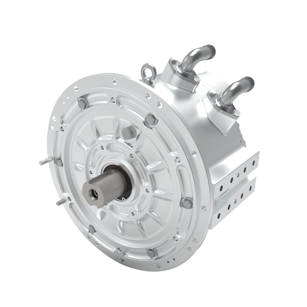
Moving forward, we must pair hardware clarity with smarter control. New principles emphasise closed-loop sensing (not just estimated back-EMF), robust calibration against temperature drift, and controllers that adapt their observers to changing conditions. For example, advanced observers that include thermal models reduce guesswork. When we discuss a modern brushless motor, I expect the controller to handle flux weakening gracefully, to limit torque ripple, and to report health metrics in plain terms. These are not fanciful ideas; they are practical shifts in how we design and validate systems.
What’s Next — practical steps and a short checklist
Here’s how I recommend teams move: first, insist on baseline motor characterisation under the actual load profile. Second, choose control schemes that include temperature and current observers. Third, validate end-to-end with the intended power converters and supply conditions. — funny how that works, right? These steps cut down trial-and-error and surface hidden couplings early on. Now, to close with something actionable: three metrics you should use when evaluating a motor-control solution are 1) delivered torque stability (measured over your duty cycle), 2) thermal margin at peak power, and 3) diagnostic transparency — how clearly the system reports faults and degradation. I prefer these because they focus on what users feel, not just lab numbers. In my view, those measures separate hopeful specs from reliable gear. For teams shopping or designing today, keep them front and centre. And if you want a practical partner who understands the trade-offs, consider looking into Santroll — they know the ropes and will talk plain about performance.
