
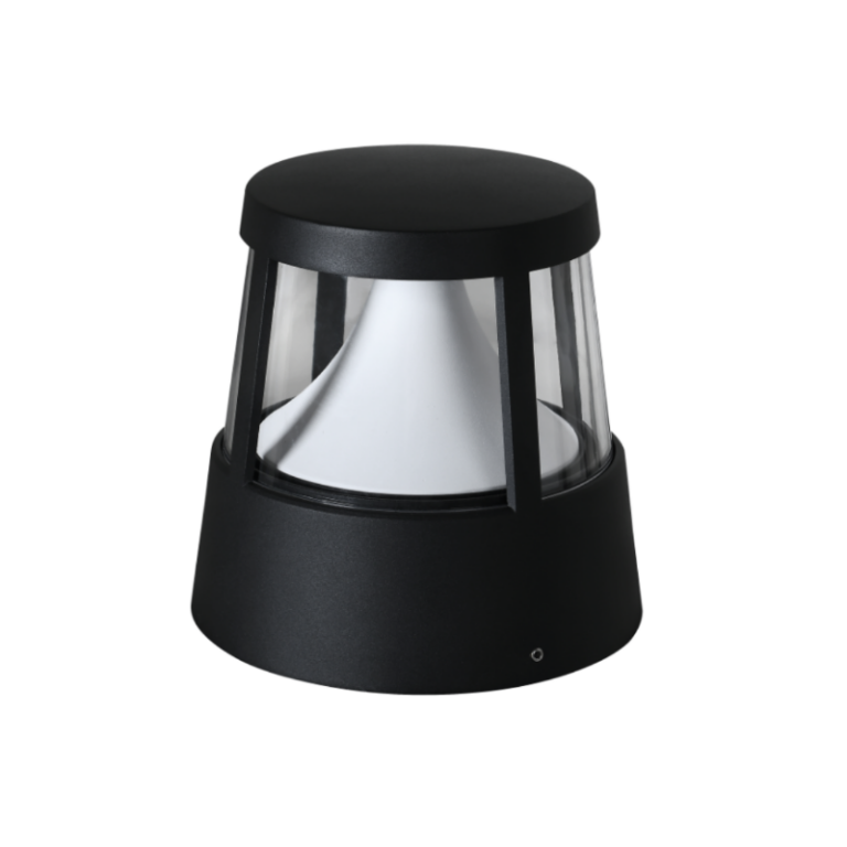
Opening the problem: why a framework helps
Deploying bollard lighting across campuses, parks, and waterfront promenades forces a series of trade-offs: better sealing prevents moisture intrusion but can raise internal temperatures; more rugged drivers improve survival but add cost and complexity. Because those trade-offs compound across hundreds of fixtures, a clear framework turns abstract specs into predictable lifetimes and service budgets. Many sites — from corporate campuses to marinas — also use complementary fixtures such as outdoor pier mount lights, and the same cause‑and‑effect rules apply across those product families. This piece uses a stepwise framework (assess, match, design) grounded in IEC 60529 IP conventions and common field realities so design choices map directly to driver longevity and operational uptime.
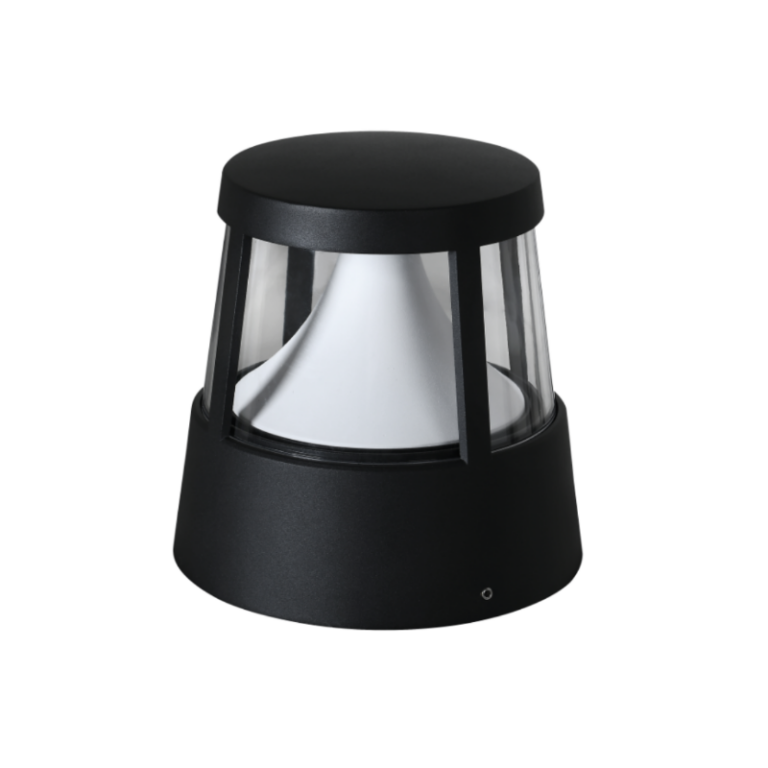
Step 1 — Assess environmental risk and choose an appropriate IP rating
Because environmental factors dictate failure modes, start by mapping exposure: splash, salt spray, dust, vandal risk, and UV. The IEC 60529 standard defines IP ratings; for example, IP65 resists jets and dust while IP67 tolerates immersion. Choosing a higher IP rating reduces ingress protection failures but increases enclosure sealing requirements — which in turn affects thermal management. For coastal bollards or pier applications, designers often specify IP66/67 because salt-driven corrosion and spray accelerate failure. Select an IP rating that matches the environment, then factor in how that rating will change internal temperature rise and serviceability.
Step 2 — Match LED driver architecture to sealing strategy
Because sealed enclosures trap heat, driver selection must compensate. A sealed (high-IP) bollard with a permanently potted driver may survive ingress but suffer accelerated lumen depreciation and reduced MTBF if thermal dissipation is inadequate. Conversely, accessible, serviceable drivers allow easier replacement but require gasketing and maintenance protocols to preserve ingress protection over time. Key driver choices include constant‑current vs. constant‑voltage, potted vs. replaceable modules, and integrated surge protection. Match a cooler‑running constant‑current driver with adequate thermal derating to the level of enclosure sealing — and specify steady-state junction temperature limits in the contract to make the expected lifetime measurable.
Step 3 — Design for maintenance, diagnostics, and network topology
Because even the best components age, proactive maintenance planning extends life without over‑engineering. Implement modular compartments or removable top caps so drivers can be swapped without compromising seals on the entire bollard. Add simple diagnostics — onboard temperature sensors, status LEDs, or networked telemetry — so hotspots are detected before failure. When fixtures are part of a distributed network, standardize driver interfaces and logging so a single spare module can service many units. This approach reduces mean time to repair and keeps long‑term costs predictable.
Common mistakes and practical mitigations
Typical missteps arise from treating IP rating as a single‑dimension fix rather than part of a system:
- Over‑specifying IP without thermal analysis — leads to hidden driver stress. Mitigation: run enclosure thermal simulations or simple steady‑state tests.
- Assuming all drivers are equal — results in premature lumen depreciation. Mitigation: require driver datasheets showing thermal derating curves and surge immunity.
- Neglecting maintenance access — creates service costs and broken seals. Mitigation: design removable driver trays or quick‑release lids with verified gasketing.
Also consider the site context — marinas and piers demand higher corrosion resistance and often pair bollards with modern pier mount lights that share drivers or control networks, so standardization saves inventory and labor.
Quantifying trade-offs: simple metrics to specify
Because clear metrics convert design intent into enforceable requirements, include these in procurement documents: expected driver lifetime at specified ambient (e.g., 50,000 hours L70 at 25°C ambient), allowable junction temperature rise, surge immunity rating (e.g., 10 kV/5 kA as a baseline for industrial settings), and ingress test evidence (IP verification reports). Require first‑article thermal cycling and a sample installation test run — those samples reveal integration issues that paperwork misses.
Three golden rules for evaluating IP and driver strategies
1) Prioritize system‑level reliability: evaluate IP rating, driver thermal derating, and access design together — because one weak link defines field life.
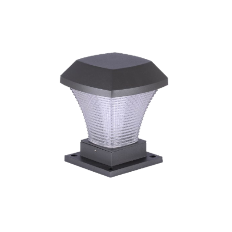
2) Insist on measurable specs: require driver MTBF figures tied to explicit ambient temperatures and documented IP test certificates under IEC 60529.
3) Design for replaceability and diagnostics: reduce lifecycle cost by making drivers serviceable and instrumenting fixtures for early warning.
Apply this framework and you convert vague promises into predictable performance — fewer unexpected outages, lower lifecycle costs, and clearer budgets for spares and maintenance. For real‑world perspective: municipalities that shifted from generic sealed bollards to a matched IP/driver approach commonly see a reduction in unscheduled repairs and a longer interval between full replacements — results you can project into procurement decisions. —
Keyida. —
